Electrical reference
Wire Resistance Chart
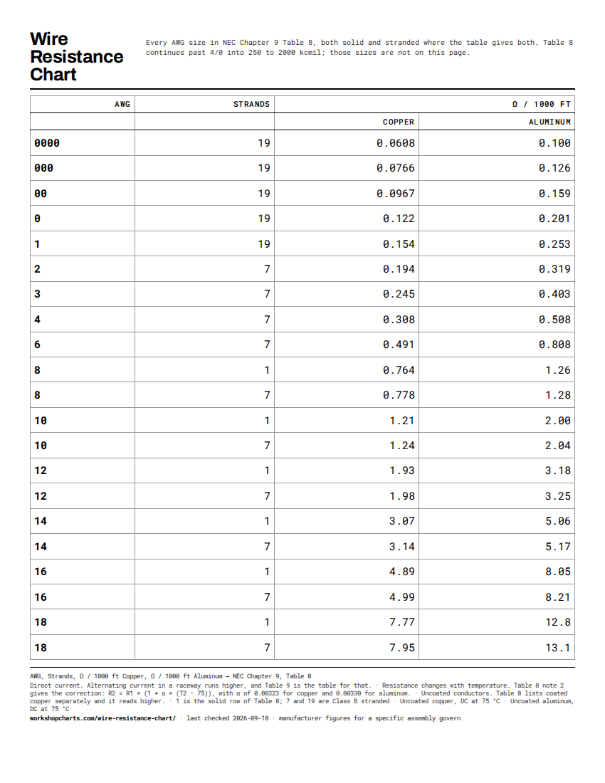
DC resistance of copper and aluminum conductors at 75 °C, in ohms per 1000 feet, for sizing a run against voltage drop.
- Basis Sight-checked
- Last checked 2026-09-18
- Sheet portrait
Both unit systems load with the page. The filter searches every column.
| AWG | Strands | Ω / 1000 ft | |
|---|---|---|---|
| Copper | Aluminum | ||
| 0000 | 19 | 0.0608 | 0.100 |
| 000 | 19 | 0.0766 | 0.126 |
| 00 | 19 | 0.0967 | 0.159 |
| 0 | 19 | 0.122 | 0.201 |
| 1 | 19 | 0.154 | 0.253 |
| 2 | 7 | 0.194 | 0.319 |
| 3 | 7 | 0.245 | 0.403 |
| 4 | 7 | 0.308 | 0.508 |
| 6 | 7 | 0.491 | 0.808 |
| 8 | 1 | 0.764 | 1.26 |
| 8 | 7 | 0.778 | 1.28 |
| 10 | 1 | 1.21 | 2.00 |
| 10 | 7 | 1.24 | 2.04 |
| 12 | 1 | 1.93 | 3.18 |
| 12 | 7 | 1.98 | 3.25 |
| 14 | 1 | 3.07 | 5.06 |
| 14 | 7 | 3.14 | 5.17 |
| 16 | 1 | 4.89 | 8.05 |
| 16 | 7 | 4.99 | 8.21 |
| 18 | 1 | 7.77 | 12.8 |
| 18 | 7 | 7.95 | 13.1 |
No size matches that. Clear the filter to see the full table.
Sources mapped to columns
One line per source, listing exactly which columns it covers. A column cannot appear in the table without appearing here, because the build fails on it.
| Columns | Source | Basis |
|---|---|---|
| AWG Strands Ω / 1000 ft Copper Ω / 1000 ft Aluminum | NEC Chapter 9, Table 8 (2026) NFPA Direct-current resistance at 75 °C of uncoated copper and aluminum conductors in ohms per 1000 ft, with the stranding each figure belongs to. Table 8 gives a solid and a stranded row for 18 through 8 AWG, and Class B stranded only from 6 AWG up. No publisher page: NFPA publishes the code for reading at no charge after sign-in. | Published standard |
Conditions
- Direct current. Alternating current in a raceway runs higher, and Table 9 is the table for that.
- Resistance changes with temperature. Table 8 note 2 gives the correction: R2 = R1 × (1 + α × (T2 − 75)), with α of 0.00323 for copper and 0.00330 for aluminum.
- Uncoated conductors. Table 8 lists coated copper separately and it reads higher.
- 1 is the solid row of Table 8; 7 and 19 are Class B stranded
- Uncoated copper, DC at 75 °C
- Uncoated aluminum, DC at 75 °C
Checked against the standards above by Denis · 2026-09-18
Where the equipment manufacturer specifies a figure for the specific assembly, that figure governs. This is a reference sheet, not a substitute for the instructions that came with the part.
One data set. Two purpose-built sheets.
The printable sheet and the vertical image use different layouts, so neither one sacrifices readability to the other.
 Download PDF
 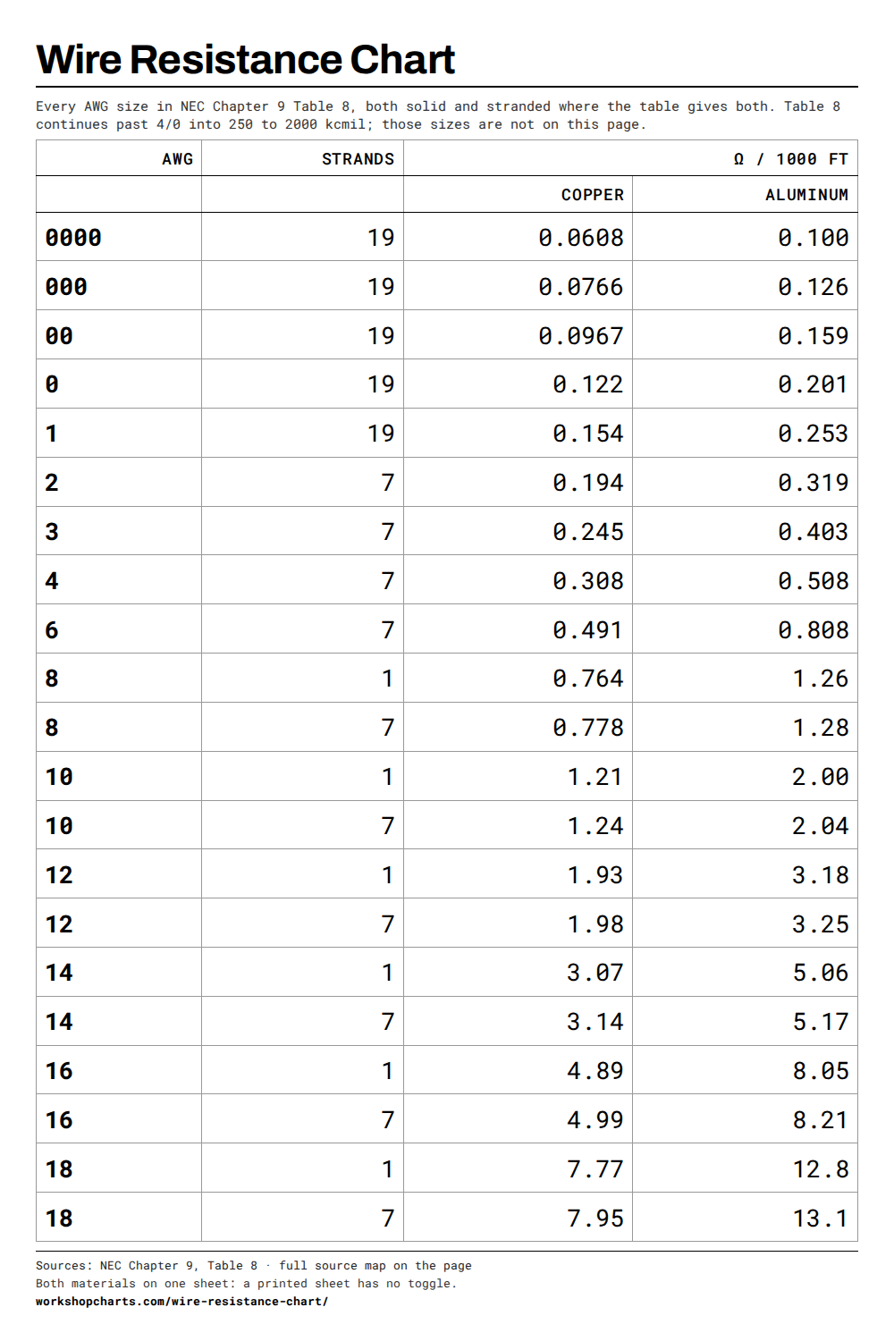 Download PNG
 Both materials on one sheet: a printed sheet has no toggle.
How to use this chart
- Find the conductor size, then the row whose strand count matches what you are actually pulling. Six sizes appear twice because the standard gives both a solid and a stranded figure for them.
- Read the column for the metal. The figure is ohms for 1000 feet of one conductor.
- A circuit runs out and back, so a 50 ft run is 100 ft of conductor.
- Voltage drop is that resistance times the current: ohms per 1000 ft, times feet of conductor, divided by 1000, times amps.
Frequently asked questions
Why do some sizes appear twice?
Because Table 8 lists them twice. From 18 through 8 AWG a conductor may be solid or stranded, and the two read differently: stranded is about 2 to 3 percent higher for the same size, because the strands spiral and the path is longer than the cable. From 6 AWG up the table lists Class B stranded only. The strand column says which row is which.
Why is aluminum higher than copper for the same gauge?
Aluminum conducts less well by volume. Table 8 note 4 puts bare copper at 100 percent and aluminum at 61 percent on the international annealed copper standard, which is why the aluminum figures run about 1.6 times the copper ones and why an aluminum run is normally sized up.
Why does the chart stop at 4/0 and at 18 AWG?
Table 8 continues past 4/0 into 250 through 2000 kcmil, which are service and feeder sizes rather than the sizes this page is for. Below 18 AWG the table stops: the wire gauge chart carries those sizes with diameter and area, computed from the AWG definition, but no document cited here gives them a resistance figure.
Is this the right figure for an AC circuit?
Not exactly. These are direct-current values. For alternating current in a raceway the effective resistance is higher, and NEC Chapter 9 Table 9 is the table written for that case.