Electrical reference
Wire Ampacity Chart
Allowable ampacity of copper and aluminum conductors under NEC Table 310.16, with the 240.4(D) limit on the breaker or fuse beside it.
- Basis Sight-checked
- Last checked 2026-09-18
- Sheet landscape
Both unit systems load with the page. The filter searches every column.
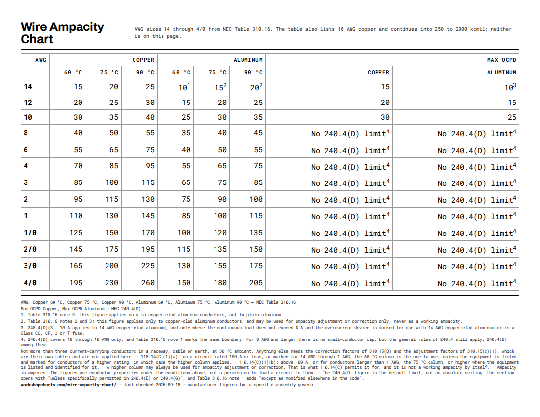
| AWG | Copper | Aluminum | Max OCPD | |||||
|---|---|---|---|---|---|---|---|---|
| 60 °C | 75 °C | 90 °C | 60 °C | 75 °C | 90 °C | Copper | Aluminum | |
| 14 | 15 | 20 | 25 | 10 1 | 15 2 | 20 2 | 15 | 10 3 |
| 12 | 20 | 25 | 30 | 15 | 20 | 25 | 20 | 15 |
| 10 | 30 | 35 | 40 | 25 | 30 | 35 | 30 | 25 |
| 8 | 40 | 50 | 55 | 35 | 40 | 45 | No 240.4(D) limit 4 | No 240.4(D) limit 4 |
| 6 | 55 | 65 | 75 | 40 | 50 | 55 | No 240.4(D) limit 4 | No 240.4(D) limit 4 |
| 4 | 70 | 85 | 95 | 55 | 65 | 75 | No 240.4(D) limit 4 | No 240.4(D) limit 4 |
| 3 | 85 | 100 | 115 | 65 | 75 | 85 | No 240.4(D) limit 4 | No 240.4(D) limit 4 |
| 2 | 95 | 115 | 130 | 75 | 90 | 100 | No 240.4(D) limit 4 | No 240.4(D) limit 4 |
| 1 | 110 | 130 | 145 | 85 | 100 | 115 | No 240.4(D) limit 4 | No 240.4(D) limit 4 |
| 1/0 | 125 | 150 | 170 | 100 | 120 | 135 | No 240.4(D) limit 4 | No 240.4(D) limit 4 |
| 2/0 | 145 | 175 | 195 | 115 | 135 | 150 | No 240.4(D) limit 4 | No 240.4(D) limit 4 |
| 3/0 | 165 | 200 | 225 | 130 | 155 | 175 | No 240.4(D) limit 4 | No 240.4(D) limit 4 |
| 4/0 | 195 | 230 | 260 | 150 | 180 | 205 | No 240.4(D) limit 4 | No 240.4(D) limit 4 |
- Table 310.16 note 3: this figure applies only to copper-clad aluminum conductors, not to plain aluminum.
- Table 310.16 notes 2 and 3: this figure applies only to copper-clad aluminum conductors, and may be used for ampacity adjustment or correction only, never as a working ampacity.
- 240.4(D)(3): 10 A applies to 14 AWG copper-clad aluminum, and only where the continuous load does not exceed 8 A and the overcurrent device is marked for use with 14 AWG copper-clad aluminum or is a Class CC, CF, J or T fuse.
- 240.4(D) covers 18 through 10 AWG only, and Table 310.16 note 1 marks the same boundary. For 8 AWG and larger there is no small-conductor cap, but the general rules of 240.4 still apply, 240.4(B) among them.
No size matches that. Clear the filter to see the full table.
Sources mapped to columns
One line per source, listing exactly which columns it covers. A column cannot appear in the table without appearing here, because the build fails on it.
| Columns | Source | Basis |
|---|---|---|
| AWG Copper 60 °C Copper 75 °C Copper 90 °C Aluminum 60 °C Aluminum 75 °C Aluminum 90 °C | NEC Table 310.16 (2026) NFPA Allowable ampacities of insulated conductors with not more than three current-carrying conductors in a raceway, cable or earth, at 30 °C ambient, for copper and for aluminum or copper-clad aluminum at 60, 75 and 90 °C. No publisher page: NFPA publishes the code for reading at no charge after sign-in. | Published standard |
| Max OCPD Copper Max OCPD Aluminum | NEC 240.4(D) (2026) NFPA Small conductors. The maximum rating of the overcurrent device for 18 through 10 AWG, which is lower than the ampacity of the same conductor and is the figure that actually sizes a branch circuit. No publisher page: NFPA publishes the code for reading at no charge after sign-in. | Published standard |
Conditions
- Not more than three current-carrying conductors in a raceway, cable or earth, at 30 °C ambient. Anything else needs the correction factors of 310.15(B) and the adjustment factors of 310.15(C)(1), which are their own tables and are not applied here.
- 110.14(C)(1)(a): on a circuit rated 100 A or less, or marked for 14 AWG through 1 AWG, the 60 °C column is the one to use, unless the equipment is listed and marked for conductors of a higher rating, in which case the higher column applies.
- 110.14(C)(1)(b): above 100 A, or for conductors larger than 1 AWG, the 75 °C column, or higher where the equipment is listed and identified for it.
- A higher column may always be used for ampacity adjustment or correction. That is what 110.14(C) permits it for, and it is not a working ampacity by itself.
- Ampacity in amperes. The figures are conductor properties under the conditions above, not a permission to load a circuit to them.
- The 240.4(D) figure is the default limit, not an absolute ceiling: the section opens with "unless specifically permitted in 240.4(E) or 240.4(G)", and Table 310.16 note 1 adds "except as modified elsewhere in the code".
- The 240.4(D) figure is the default limit, not an absolute ceiling: the section opens with "unless specifically permitted in 240.4(E) or 240.4(G)", and Table 310.16 note 1 adds "except as modified elsewhere in the code".
Checked against the standards above by Denis · 2026-09-18
Where the equipment manufacturer specifies a figure for the specific assembly, that figure governs. This is a reference sheet, not a substitute for the instructions that came with the part.
One data set. Two purpose-built sheets.
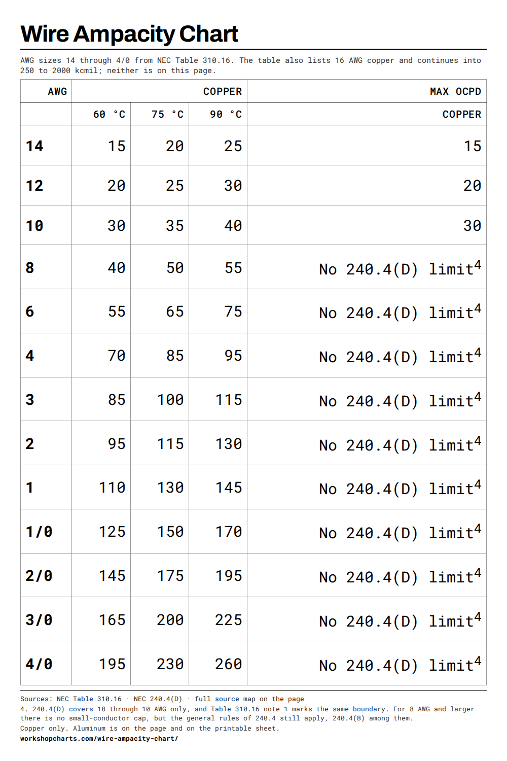
The printable sheet and the vertical image use different layouts, so neither one sacrifices readability to the other.
 Download PDF
  Download PNG
 Copper only. Aluminum is on the page and on the printable sheet.
How to use this chart
- Read the termination rating off the breaker, the panel or the device, then use the column that matches it. On a circuit rated 100 A or less, or one marked for 14 AWG through 1 AWG, that is the 60 °C column unless the equipment is listed and marked for conductors of a higher rating, in which case use the higher column.
- Check the Max OCPD column before sizing the breaker. For 14, 12 and 10 AWG it is lower than the ampacity, and it is the figure that governs.
- The 90 °C column is almost never the working ampacity. It is there so a conductor with 90 °C insulation can be used as the starting point for a correction or adjustment calculation.
- These figures assume 30 °C ambient and no more than three current-carrying conductors. A hot attic or a crowded conduit lowers them, through tables this page does not carry.
- Where the equipment manufacturer specifies a conductor for the terminal, that instruction governs over any table.
Frequently asked questions
Why is the breaker limit lower than the ampacity?
Because they answer different questions. Ampacity is how much current the conductor can carry continuously under the stated conditions. 240.4(D) limits the overcurrent device protecting small conductors, and for 14, 12 and 10 AWG it sits below the ampacity: 15 A on 14 AWG copper against 20 A of ampacity at 75 °C. The lower figure is the one that sizes the circuit.
Which temperature column should I use?
The one matching the lowest temperature rating in the connection, which 110.14(C) makes the rule. On circuits of 100 A or less, or marked for 14 AWG through 1 AWG, that is 60 °C by default, and 75 °C where the equipment is listed and marked for it. Above 100 A it is 75 °C, or higher where the equipment is listed and identified for that.
Why does the 14 AWG aluminum row carry footnotes?
Because Table 310.16 puts them there. The figures on that row apply to copper-clad aluminum, not to plain aluminum, and the 75 °C and 90 °C figures may be used only for adjustment or correction rather than as a working ampacity. The row is kept because the copper side of it is the size most people come here for, and the footnotes are on the individual cells because that is where the standard puts them.
Do these numbers apply in a hot attic or a full conduit?
No. Table 310.16 assumes 30 °C ambient and not more than three current-carrying conductors. Above that ambient the figures are multiplied by the correction factors in 310.15(B), and beyond three conductors by the adjustment factors in 310.15(C)(1). Both are separate tables, and neither is applied to the figures on this page.